
The first step was to test the LED strip control circuit. I’m using a TIP120 here; they are not as efficient as a MOSFET but they have sufficient current capacity for this application and were already at hand. The resistors are both 1k ohm 1/4 watt.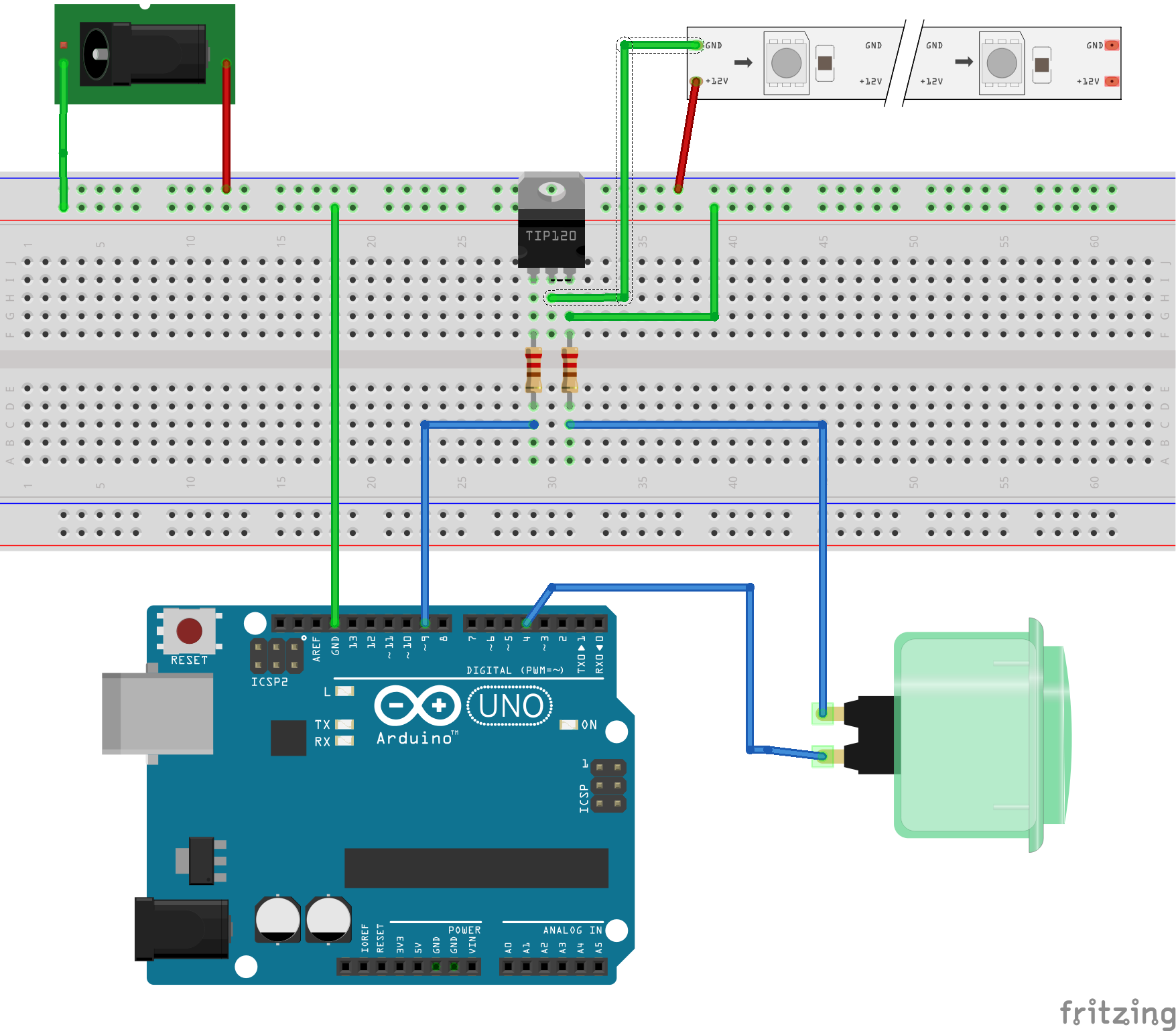
The power connector is for the 12V supply. It will eventually run the entire system but during development I’m running the Arduino from the USB connection. With this built I can start to work on the software.
The button will toggle the LED strip on/off. I didn’t want a hard on/off transition so I added a ramp effect to soften the transition from dark to light.
<soapbox> Something you, dear reader, need to bear in mind when reading my code; I write for clarity not efficiency. Although I am new to the Arduino environment (Processing) I have been coding for a rather long time. One thing I’ve learned along the way is that the ‘clarity of purpose’ of any section of code is far more valuable than squeaking out a few nanoseconds of execution time/bytes of storage space. There are, of course, exceptions to this maxim (see below) but if you ever hope to maintain this code in the future, or, to share it with someone who does not share your brain you will do well to avoid ‘tricks’ or ‘elegant but not obvious’ code. </soapbox>
That said, here is my code to exercise the circuit above.
/*
 Clock LED controller - phase 1

 2015-jan-31 TimC
  First Go - simple push button control with LED ramp up/down

 -- Other code
 Btn Debounce code by David A. Mellis, Limor Fried & Mike Walters
 */

const char *SW_TITLE = "Grandfather clock LED lighting controller";
const char *SW_VER = "p1";

// constants won't change. They're used here to
// set pin numbers:
const byte btnPIN= 4;     // the number of the pushbutton pin - Pin 2 on first board is hosed
const byte ledPIN = 9;    // the number of the LED pin

// Variables will change:
int ledBright = FULL_OFF;         // the current LED brightness 0 - 255
int ledState = LOW;              // are the LEDs on?
int ledChange = LOW;             // Did LED state change in this loop cycle?
int btnState = LOW;             // the current reading from the input pin
int lastBtnState = btnState;   // the previous reading from the input pin

// the following variables are long's because the time, measured in miliseconds,
// will quickly become a bigger number than can be stored in an int.
long lastDebounceTime = 0;  // the last time the output pin was toggled
long debounceDelay = 100;    // the debounce time; increase if the output flickers

//======================================
void setup() {
//======================================
char buff[50];

  Serial.begin(9600);           // set up Serial library at 9600 bps
  sprintf(buff, "%s v%s", SW_TITLE, SW_VER );
  Serial.println( buff );

  pinMode(btnPIN, INPUT);
  pinMode(ledPIN, OUTPUT);

  // set initial LED state
  analogWrite(ledPIN, ledBright);

}

//==============================
void loop() {
//==============================
  ledChange = LOW;        // no change so far

  // read the state of the switch
  int reading = digitalRead( btnPIN );

  // check to see if you just pressed the button
  // (i.e. the input went from LOW to HIGH),  and you've waited
  // long enough since the last press to ignore any noise:

  // If the switch changed, due to noise or pressing:
  if (reading != lastBtnState) {
    // reset the debouncing timer
    lastDebounceTime = millis();
  }

  if ((millis() - lastDebounceTime) > debounceDelay) {
    // whatever the reading is at, it's been there for longer
    // than the debounce delay, so take it as the actual current state:
    // if the button state has changed:
    if (reading != btnState) {
      btnState = reading;
      Serial.print("BTN state change:");
      Serial.println( btnState );

      if( btnState == HIGH ) {
        ledState = ! ledState;
        ledChange = HIGH;
      }
    }
  }

  // save the reading.  Next time through the loop,
  // it'll be the lastButtonState:
  lastBtnState = reading;

  if ( ledChange == HIGH ) {
    if ( ledState == HIGH ) {
      ledRampBright( FULL_ON );
    } else {
      ledRampBright( FULL_OFF );
    }
  }

  delay( 200 );
}

//-----------------------------------
void ledRampBright( int target ){
//-----------------------------------
  int chg = 0;
  int incr = 1;

  if( target < 0 ) { target = FULL_OFF; }    // sanity check the parm
  if( target > 255 ) { target = FULL_ON; }

  chg = ( target - ledBright );
  if( chg < 0 ) { incr = -1; }    // we are going down, not up

  Serial.print("Ramp:target:");
  Serial.print(target);
  Serial.print(" current:");
  Serial.print( ledBright );
  Serial.print(" incr:");
  Serial.println( incr );  // prints hello with ending line break

  while ( ledBright != target ) {
    ledBright = ledBright + incr;
    analogWrite(ledPIN, ledBright);
    delay(15);                  // wait a bit
  }

  Serial.print("LED brightness set to:");
  Serial.println( ledBright );
  return;
}
With that working as desired, the next step is to add the light sensor. A simple photoresistor will do nicely here. The resistor is a 10k 1/4 watt piece. The circuit works as a voltage divider that reacts to ambient light levels. There is much more info. available here.
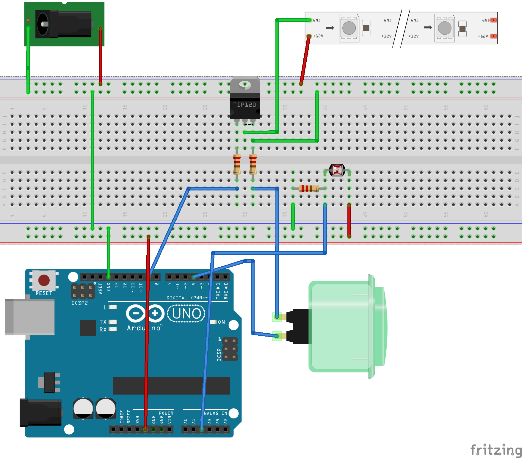
Just a few additions to the code to test this; in the constants section:
const byte lightPIN = A2;  // photoresistor pin
const int lightTHRES = 350;  // less than this is 'dark';
You will have to play with the value of lightTHRES for your environment/component values to determine an appropriate setting for your ‘dark’ threshold. And then just before the test to change the LED state:
...
 Serial.println( analogRead( lightPIN ) );

 if( analogRead( lightPIN ) < lightTHRES ) {
 Serial.println(" - Dark - enable PIR");
 }

 if ( ledChange == HIGH ) {
...
The last bit of hardware is the PIR motion sensor. You can find some more info. here and a tutorial here. I’ve moved the switch to make it a bit less cluttered on the bottom of the diagram and to clarify the connection to ground. Pay attention to the markings on your PIR sensor to verify correct polarity.
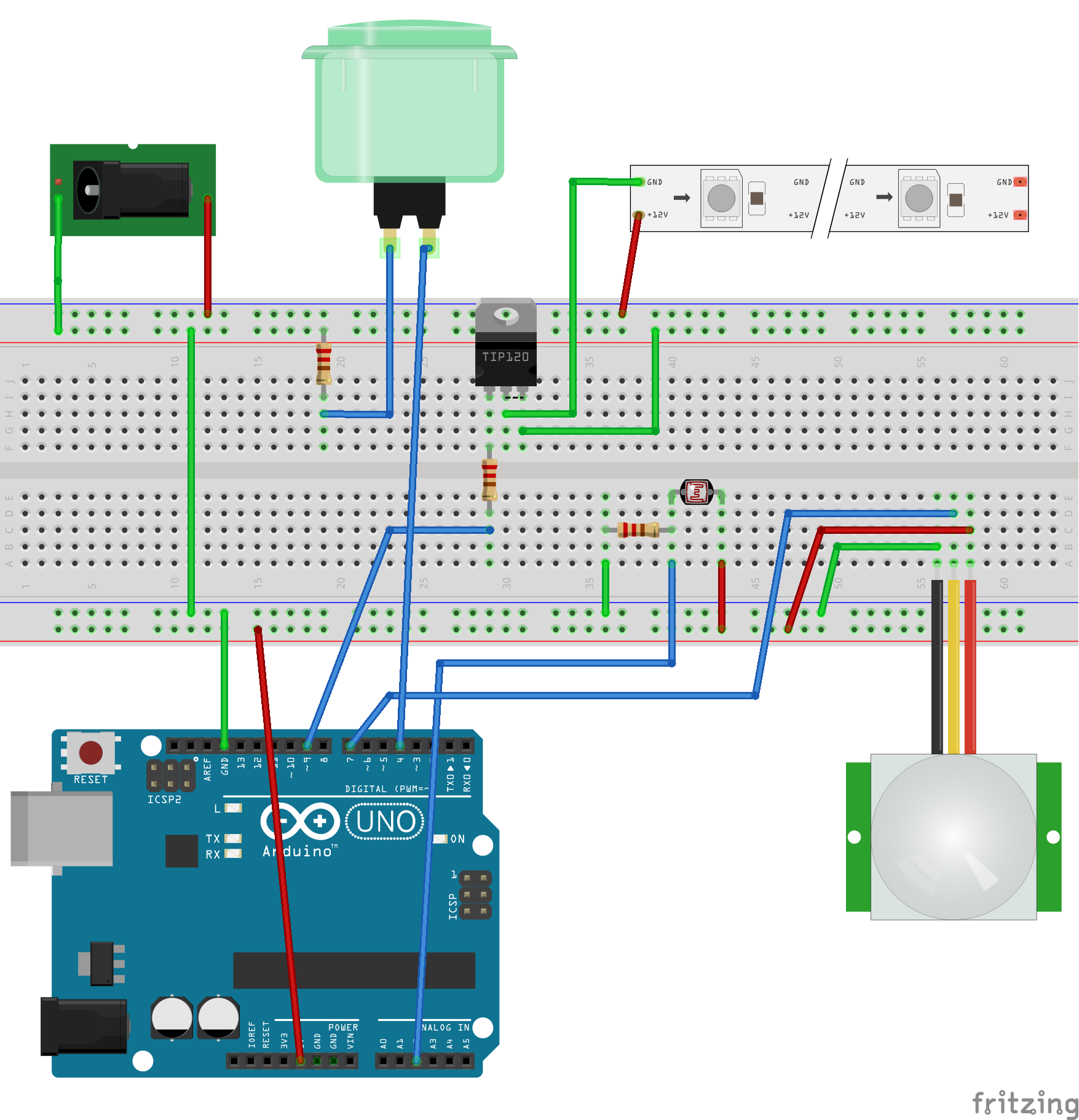
A PIR sensor requires a bit of ‘settle time’ at power up to calibrate itself to the current environment; I added a short delay during the setup() section. At this point I also added a bit of code to blink the LEDs at startup as a visual indication that the controller was working and ready.
During testing I noticed an undesirable behavior; the PIR would immediately turn the LEDs back on after manually turning them off with the switch. I added some code to ‘lock out’ the PIR sensor trigger for a period of time after the switch was pressed. This will give you time to walk away from the clock after turning the lights off.
This ‘lock out’ timer does use a bit of a trick; it is related to the way the Arduino (the Processing language actually) manages data types. You can read all about the gritty details here,or just copy my code (which is a copy from a code sample on that page). Because of the method used the lock out is limited to about 32 seconds. I’ve found that to be quite sufficient for this purpose.
The final running code is here.
/*
 Clock LED controller

 2015-jan-31 TimC
  First Go - simple push button control with LED ramp up/down

 2015-feb-2 - TimC
   Add motion sensor trigger

 2015-feb-9 - TimC
   Add photosensor
 2015-feb-10 - TimC
   Add 'blink' at startup to indicate the device is ready.
   Add 30s delay to PIR triggers after manual button press.  This allows time to walk away from unit before
    retriggering the lights.

 2015-feb-12 - TimC
   Reduce dark threshold to 400 - it was coming on too early in the day.

 2015-feb-26 - TimC
   Reduce dark threshold to 350 - it was coming on too early in the day.

 -- Other code
 Btn Debounce code by David A. Mellis, Limor Fried & Mike Walters
 */

const char *SW_TITLE = "Grandfather clock LED lighting controller";
const char *SW_VER = "20150228.2";

// constants won't change. They're used here to
// set pin numbers:
const byte btnPIN= 4;     // the number of the pushbutton pin - Pin 2 on first board is hosed
const byte ledPIN = 9;    // the number of the LED pin
const byte lightPIN = A2;  // photoresistor pin
const int lightTHRES = 350;  // less than this is 'dark';
const int FULL_OFF = 0;  // Brightness of LEDs when off
const int FULL_ON = 255;   // Brightness of LEDs when on
const int pirCALIBTIME = 10;  // Calibration time for PIR sensor (secs)
const int pirBTNDELAY = 30;    // How long to ignore PIR after a button press (secs) (do not exceed 30s because of long typing)
const int pirPIN = 7;         // on which pin is the PIR sensor?

// Variables will change:
int ledBright = FULL_OFF;         // the current LED brightness 0 - 255
int ledState = LOW;              // are the LEDs on?
int ledChange = LOW;             // Did LED state change in this loop cycle?
byte pirEnable = LOW;            // should we ignore PIR triggers?
long pirHoldExpire = 0;           // When does PIR hold expire? (millisec)
int btnState = LOW;             // the current reading from the input pin
int lastBtnState = btnState;   // the previous reading from the input pin

// the following variables are long's because the time, measured in miliseconds,
// will quickly become a bigger number than can be stored in an int.
long lastDebounceTime = 0;  // the last time the output pin was toggled
long debounceDelay = 100;    // the debounce time; increase if the output flickers

//======================================
void setup() {
//======================================
char buff[50];

  Serial.begin(9600);           // set up Serial library at 9600 bps
  sprintf(buff, "%s v%s", SW_TITLE, SW_VER );
  Serial.println( buff );

  pinMode(btnPIN, INPUT);
  pinMode(ledPIN, OUTPUT);

  // set initial LED state
  analogWrite(ledPIN, ledBright);

  pinMode(pirPIN, INPUT);
  digitalWrite(pirPIN, LOW);
  //give the PIR sensor some time to calibrate
  Serial.print("Calibrating PIR sensor");
  for(int i = 0; i < pirCALIBTIME; i++){
    Serial.print(".");
    delay(1000);
    }
  Serial.println("  PIR SENSOR ACTIVE");

  pinMode( lightPIN, INPUT );

  ledBlink();              // let 'em know we are up
}

//==============================
void loop() {
//==============================
  ledChange = LOW;        // no change so far

  // read the state of the switch
  int reading = digitalRead( btnPIN );

  // check to see if you just pressed the button
  // (i.e. the input went from LOW to HIGH),  and you've waited
  // long enough since the last press to ignore any noise:

  // If the switch changed, due to noise or pressing:
  if (reading != lastBtnState) {
    // reset the debouncing timer
    lastDebounceTime = millis();
  }

  if ((millis() - lastDebounceTime) > debounceDelay) {
    // whatever the reading is at, it's been there for longer
    // than the debounce delay, so take it as the actual current state:
    // if the button state has changed:
    if (reading != btnState) {
      btnState = reading;
      Serial.print("BTN state change:");
      Serial.println( btnState );

      if( btnState == HIGH ) {
        ledState = ! ledState;
        ledChange = HIGH;
        pirHoldExpire = ( (long)millis() + ( 1000 * pirBTNDELAY ) );    // ignore the PIR for pirBTNDELAY seconds
                                                                        // see http://www.faludi.com/2007/12/18/arduino-millis-rollover-handling/
      }
    }
  }

  // save the reading.  Next time through the loop,
  // it'll be the lastButtonState:
  lastBtnState = reading;

  // Check for PIR lockout hold due to manual button press
  if( ( (long)millis() - pirHoldExpire ) >= 0 ) {
//    Serial.println("Hold expired - Enable PIR");
    pirEnable = HIGH;
    pirHoldExpire = 0 ;      // reset timer
  } else {
    pirEnable = LOW;
  }

//  Serial.println( analogRead( lightPIN ) );

  if( analogRead( lightPIN ) < lightTHRES ) {
    pirEnable = ( pirEnable && HIGH);              // ignore the light level if we are still within 'button hold' time.
  } else {
    pirEnable = LOW;
  }

//--- PIR sensor check
  if( ( ledChange != HIGH ) and ( pirEnable ) ) {     // don't bother if we are already changing state

    if( ( ledState == LOW ) and ( digitalRead( pirPIN ) == HIGH ) ) {      // LEDs off and motion sensed
      Serial.println( "Motion detected." );
      ledState = HIGH;                      // Turn em on
      ledChange = HIGH;
    }

  }
//--- PIR END

  if ( ledChange == HIGH ) {
    if ( ledState == HIGH ) {
      ledRampBright( FULL_ON );
    } else {
      ledRampBright( FULL_OFF );
    }
  }

  delay( 200 );
}

//-----------------------------------
void ledRampBright( int target ){
//-----------------------------------
  int chg = 0;
  int incr = 1;

  if( target < 0 ) { target = FULL_OFF; }    // sanity check the parm
  if( target > 255 ) { target = FULL_ON; }

  chg = ( target - ledBright );
  if( chg < 0 ) { incr = -1; }    // we are going down, not up

  Serial.print("Ramp:target:");
  Serial.print(target);
  Serial.print(" current:");
  Serial.print( ledBright );
  Serial.print(" incr:");
  Serial.println( incr );  // prints hello with ending line break

  while ( ledBright != target ) {
    ledBright = ledBright + incr;
    analogWrite(ledPIN, ledBright);
    delay(15);                  // wait a bit
  }

  Serial.print("LED brightness set to:");
  Serial.println( ledBright );
  return;
}

//-----------------------------------
void ledBlink( ) {
//-----------------------------------
  analogWrite( ledPIN, FULL_ON );
  delay( 250 );
  analogWrite( ledPIN, FULL_OFF );
  delay( 250 );
  analogWrite( ledPIN, FULL_ON );
  delay( 250 );
  analogWrite( ledPIN, FULL_OFF );
  delay( 250 );
  analogWrite( ledPIN, ledBright );

  return;
}
Next step, fabrication and install!