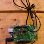
When it came time to integrate this into the clock my goal was to make it as invisible as possible and to make the fewest alterations to the clock itself. I decided to put the electronics on the top of the clock. It is high enough that only a very tall person would see it, require only a few small holes in the cabinet and readily accessible for the inevitable repair & upgrades.
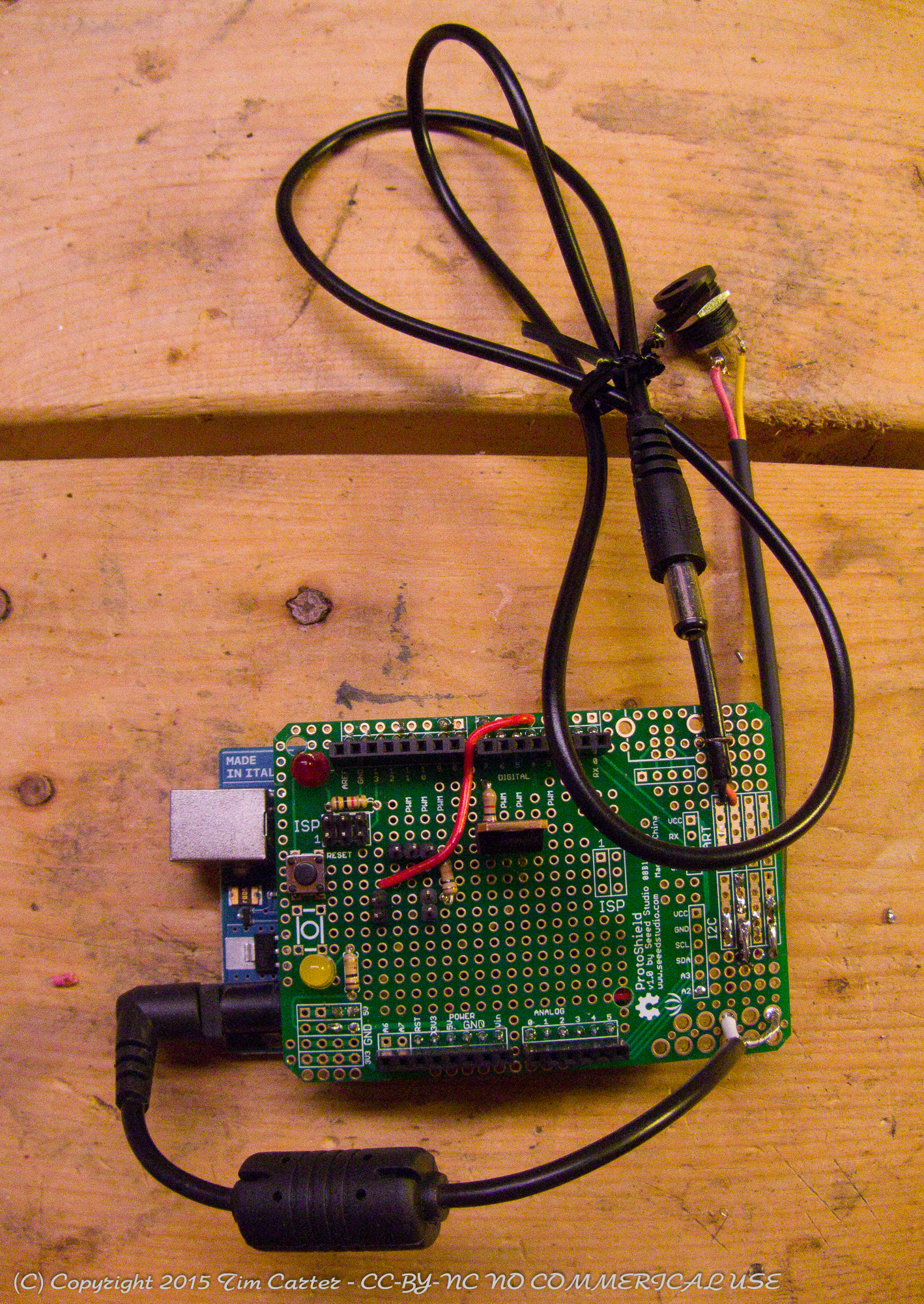
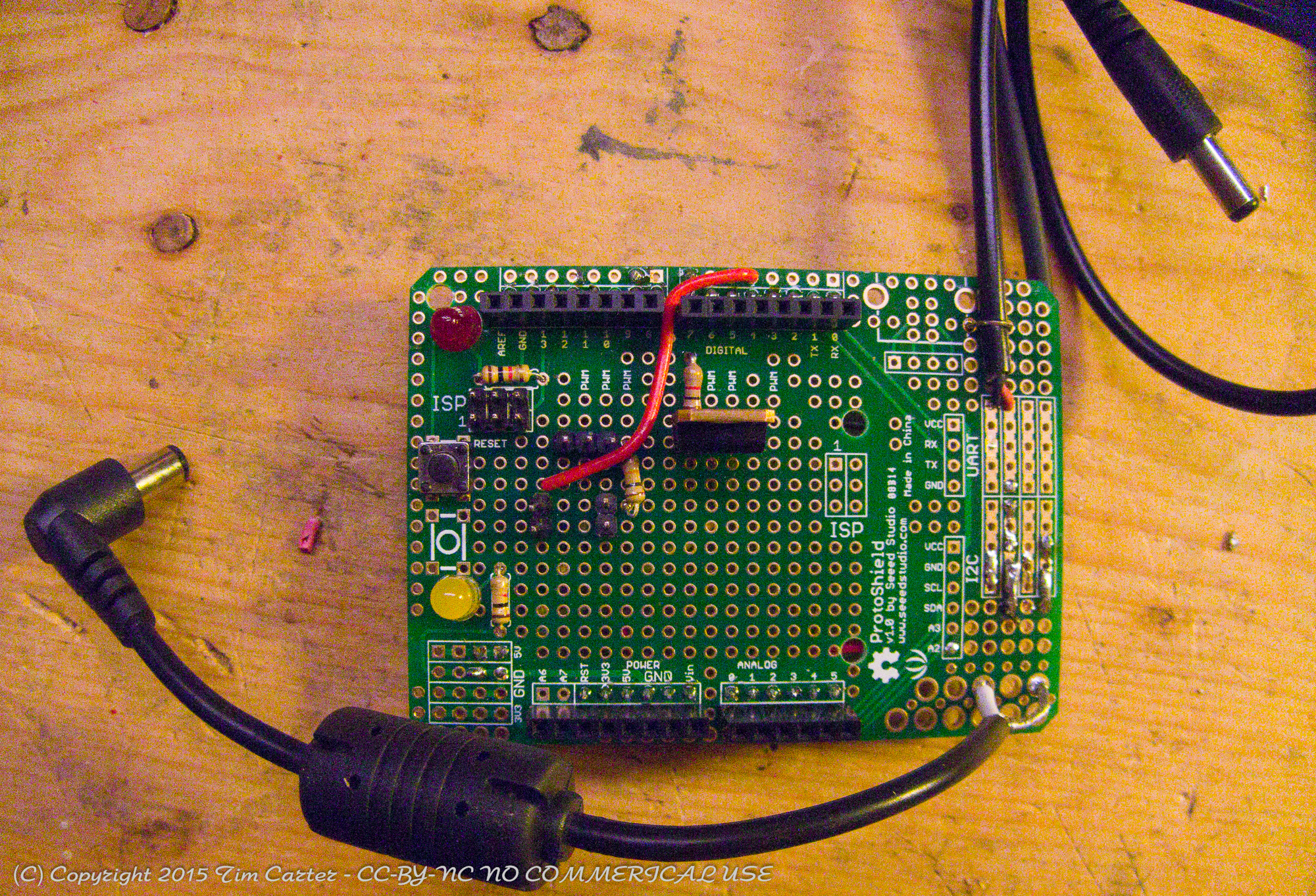
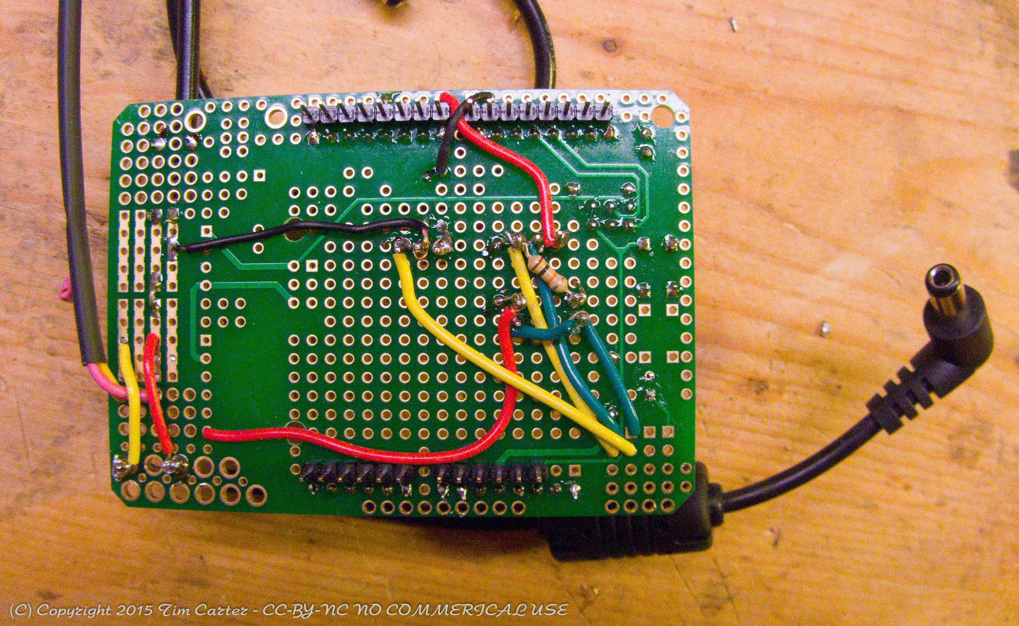
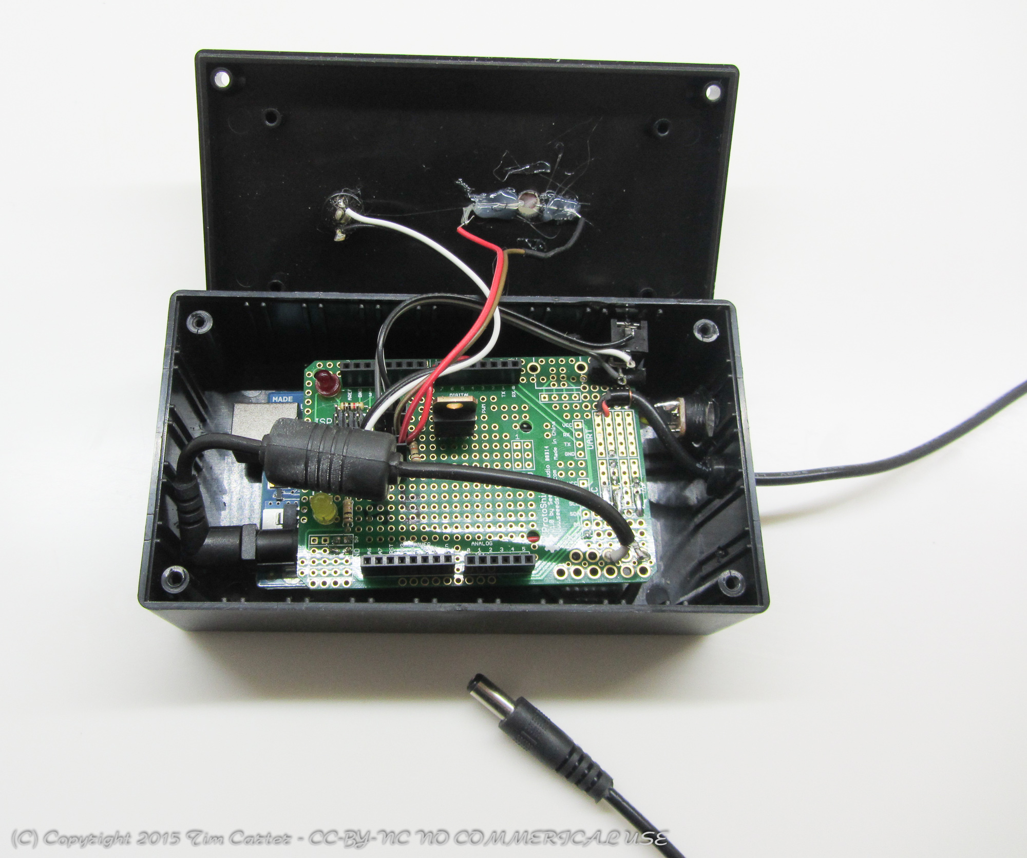
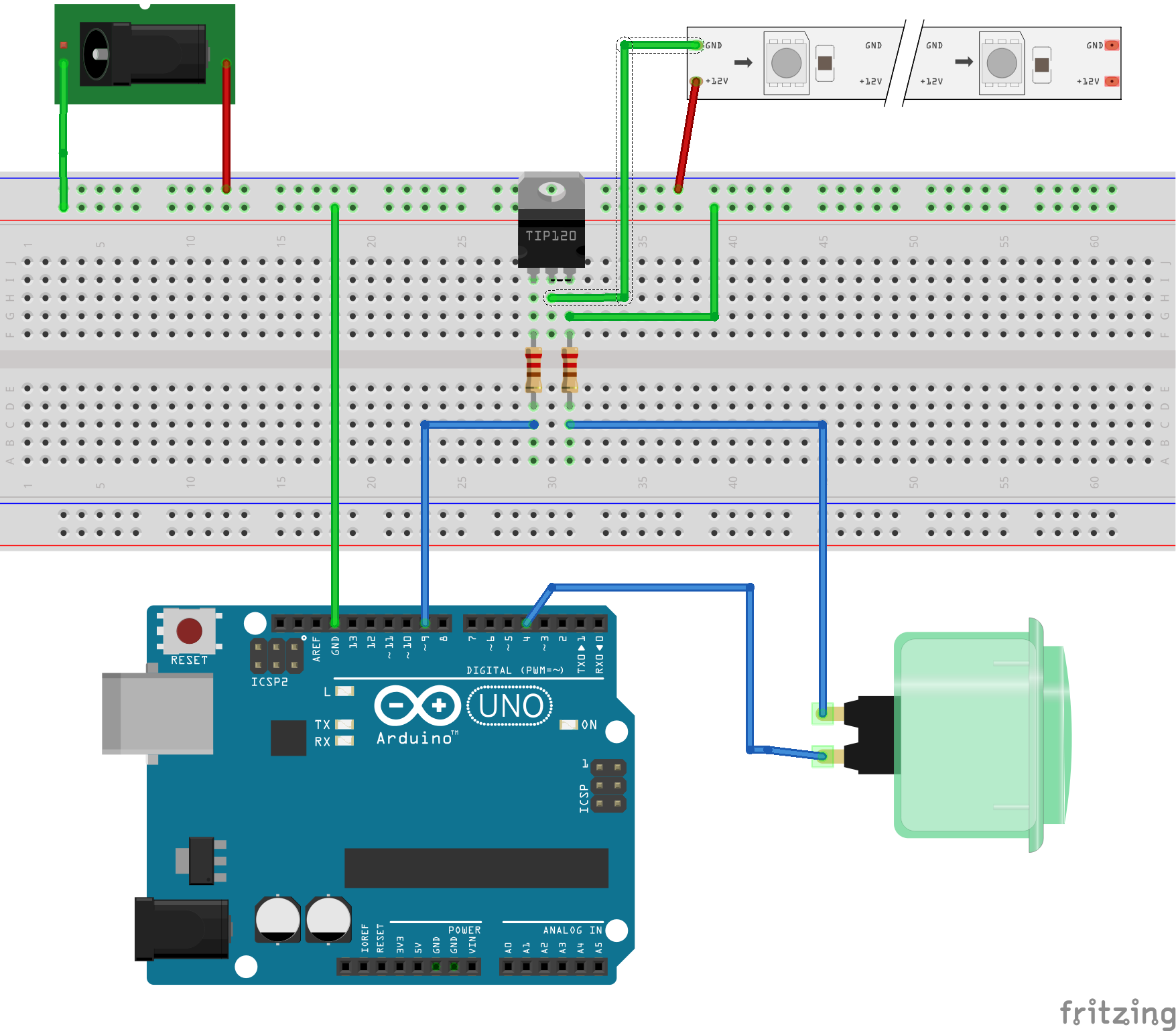
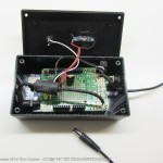
I put the circuit together on a Seeed Studios protoshield because I had one at hand. It has plenty of room for upgrades and was quite easy to work with. I added a pig-tail to connect the incoming 12v supply to the Arduino Uno board and a separate power connector to feed the LED strips. I also used pin headers for the connections to the PIR sensor, button and photoresistor. These parts will be mounted to the case so I wanted to make it easy to remove the electronics without breaking out the iron.

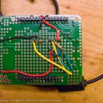
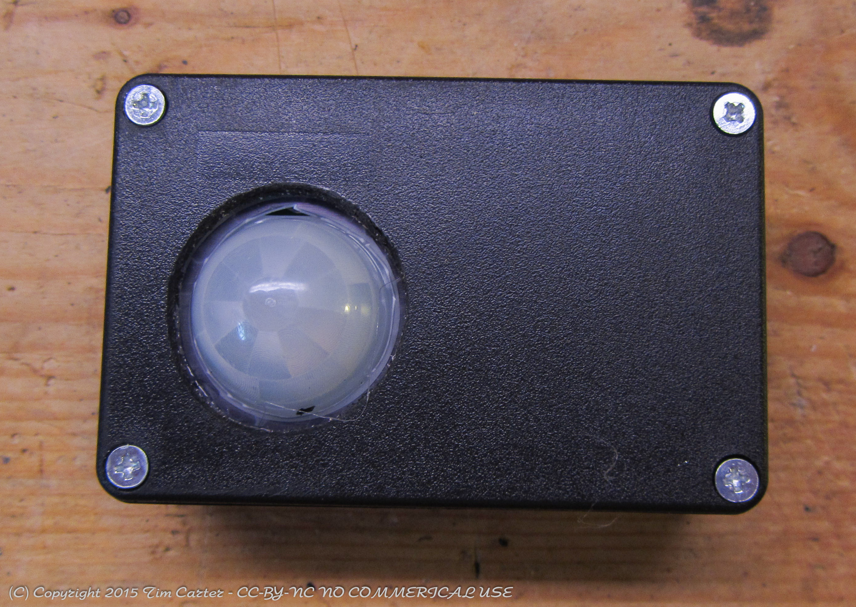
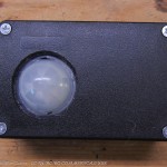
I swapped the huge arcade button for a much smaller push-button mainly because I didn’t have a drill big enough to make a hole for the arcade button. I did manage to get it shoe-horned into a small case along with a small top mounted hole for the photo sensor. I mounted the PIR sensor in a separate case so I could move it around the clock for best performance in the space. The are connected with standard 1/8 inch stereo audio cables. I mounted the PIR sensor well off-center in the case so that I could stand it on one end and have it extend past the trim piece on the top of the cabinet.
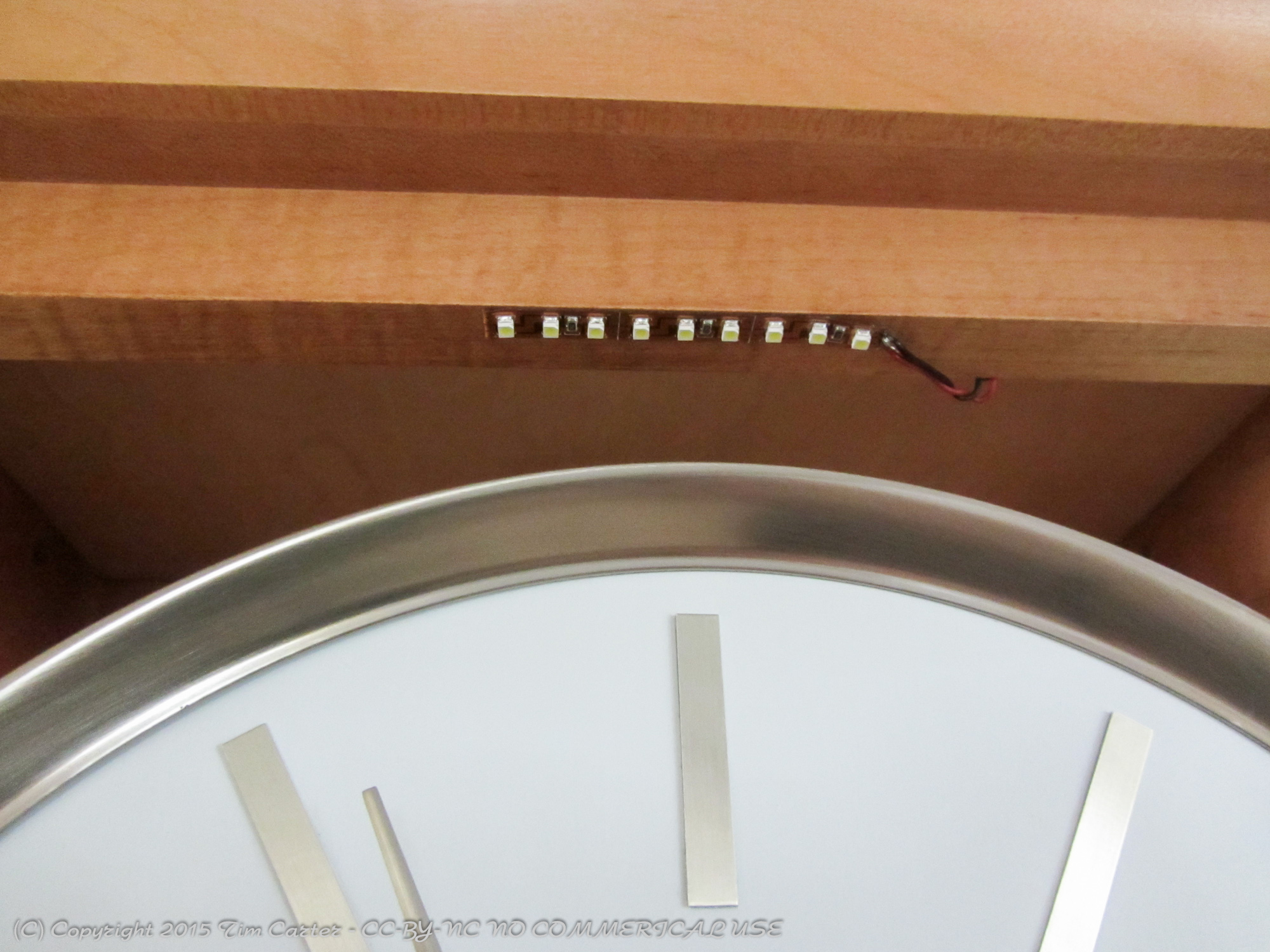
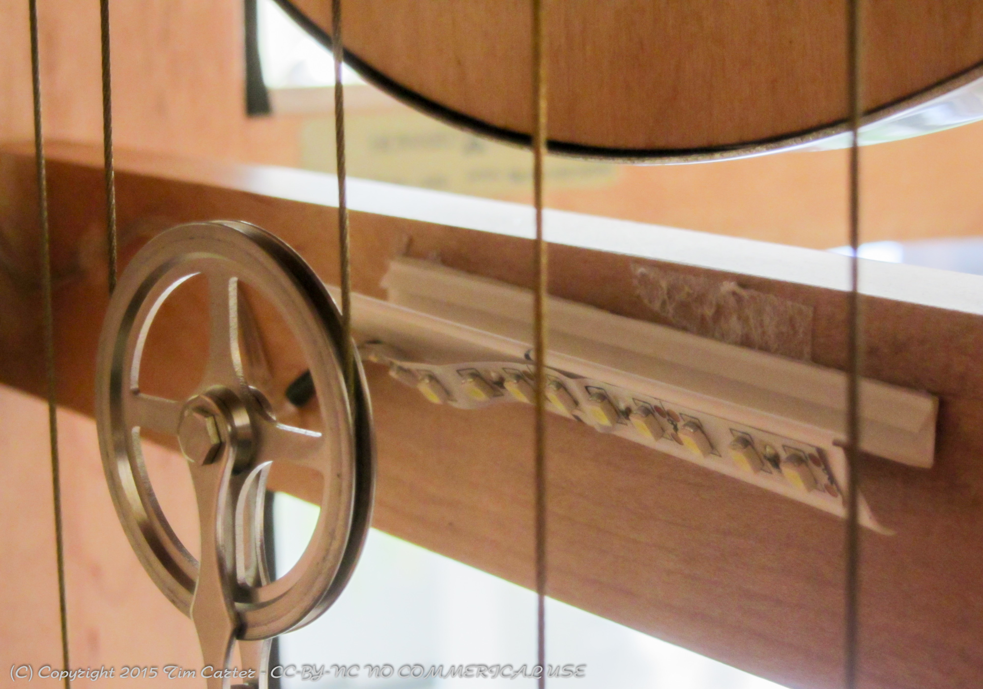
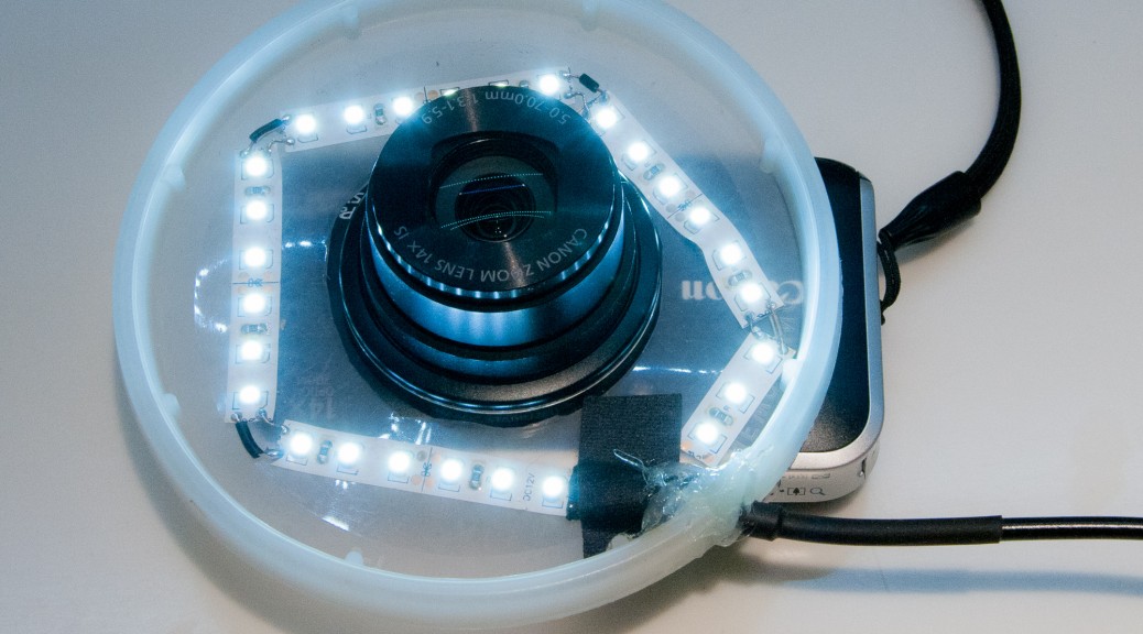
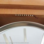
After taking a very deep breath, I drilled a small hole in top of the cabinet into the interior of the clock. I positioned the hole close to a corner so I could route the wires in the least visible place. I did not want to see the wires or LED strips from the outside of the clock but I wanted the clock face and mechanism to be lit. After considerable testing I found that mounting one strip on the top door frame facing down lit the face nicely while a strip on one of the cross members facing inwards highlighted the mechanism quite nicely. I had a small piece of weather stripping on my bench (don’t ask) and that provided a nice downward facing angle for the mechanism strip.
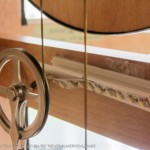
I did have a bit of trouble getting the LED strip to stick to the plastic weatherstripping — a touch of hot glue took care of that. The last step was to route the wires to the LED strips. I used 22 gauge clear speaker wire. I tacked it to the cabinet with a bit more hot clue to the hinge side of the door. It is quite invisible unless you completely open the door. I put the control box on the top of the cabinet well back from the edge so you cannot see it. The PIR sensor is all that is visible but it small enough to be unobtrusive. The entire contraption is powered by a small 12v 1.2A wall wart.
Overall I am quite pleased with the result. It does cast a very nice light onto the clock face and mechanism and provides a small amount of general lighting to the area; just enough for when we are making snack runs from the TV room to the kitchen. 😉
Two things are less-than perfect. You can see the individual LEDs in the reflections around the clock face. I could solve this with a bit of diffusion plastic on the LED strip but… meh, it’s not really that noticeable. Secondly, it occasionally goes into these on-off-on-off… death cycles. The only way to interrupt it is to remove the power. I’ve looked at the code and I can’t figure out how this is happening. At the moment it is rare enough that I just live with it.
I’ll post a video of it in operation when I have a few extra minutes.
Questions are invited!